MPO Breakout Cable in Modern Fiber Infrastructure
The MPO breakout cable has become a central component in high-density fiber deployments. As data centers scale to meet bandwidth demands, network engineers are rethinking how fiber is routed and terminated. This shift has pushed breakout configurations from niche applications into mainstream infrastructure planning.
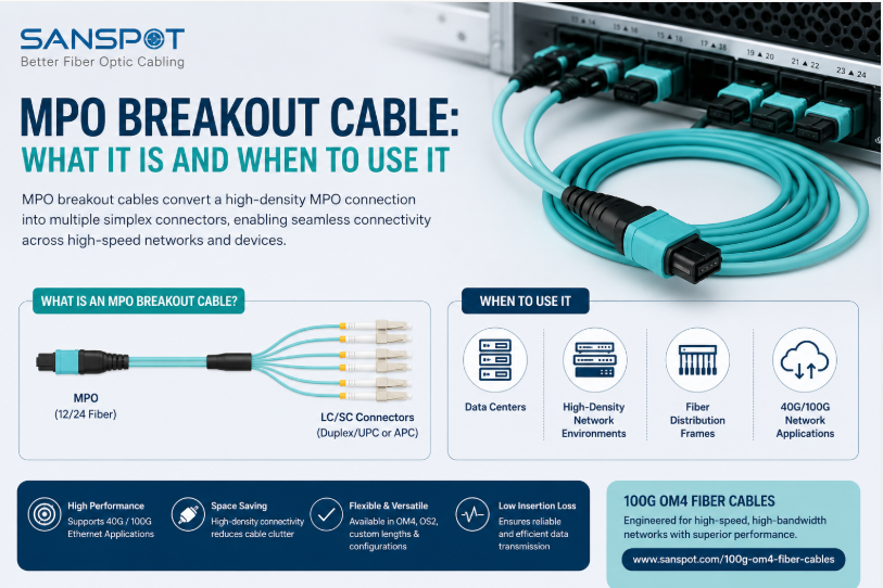
An MPO breakout cable converts a single multi-fiber MPO connector into multiple individual fiber connectors. Each individual fiber typically terminates in an LC, SC, or ST connector. This allows one high-density MPO trunk to fan out and connect directly to multiple devices or panels.
How the MPO Breakout Cable Architecture Works
The construction relies on an MPO connector at one end holding 8, 12, or 24 fibers. At the other end, those fibers split into individual legs. Each leg carries one or two fibers depending on the application.
According to the Telecommunications Industry Association (TIA), structured cabling systems using MPO-based architectures support migration paths from 10G to 100G without full infrastructure replacement. This makes breakout cabling a practical investment for facilities planning phased upgrades. The flexibility of the fan-out design avoids costly re-termination when equipment changes.
There are two primary types: harness-style and furcation-style. Harness cables use a flexible furcation tube protecting each individual fiber leg. Furcation-style cables encase all legs within a single outer jacket before splitting at the breakout point.
Key Applications Driving Adoption
MPO fan-out cables are widely used in the following scenarios:
- Top-of-rack switch connections: Servers and switches using duplex transceivers connect directly from a single MPO port via individual LC connectors.
- Parallel optic systems: 40G and 100G parallel optic modules use MPO interfaces that fan out to multiple 10G lanes.
- Migration deployments: Existing duplex infrastructure is extended by introducing MPO breakout assemblies at aggregation points.
- Pre-terminated systems: Data centers using plug-and-play architectures rely on breakout assemblies to reduce field termination time.
According to IDC, global data center construction spending reached $48 billion in 2023, with structured cabling representing a significant portion of interior infrastructure costs. High-density MPO solutions help control that spending by consolidating fiber count per pathway.
Polarity management is a critical consideration when deploying any MPO fiber breakout assembly. TIA-568 defines three polarity methods, labeled Method A, B, and C. Choosing the wrong method causes cross-connections that are difficult to troubleshoot after installation.
Insertion loss is another performance factor. IEEE 802.3 standards specify maximum channel loss budgets for 10G, 40G, and 100G Ethernet. Each connector interface in a breakout path consumes a portion of that budget, so minimizing connector count matters.
Key Takeaways
The MPO breakout cable addresses the practical challenge of connecting high-density trunk fiber to individual device ports. It supports scalable, phased upgrades across multiple generations of equipment. As bandwidth demands continue climbing, breakout assemblies will remain a foundational tool in structured fiber design. Engineers who understand polarity, loss budgets, and connector types will deploy these assemblies more effectively and avoid common installation errors.